TI CC2540 – Dev Kit
Texas Instrument manufactures an integrated BLE chip called CC2540. This chip contains not only the bluetooth LE radio, but also programmable 8051 core. They provide complete development tools, and they come in two forms:
The larger of the devkit CC2540DK contains general-purpose development / evaluation board called SmartRF05EB. These boards are also used for their line of wireless modules created by ChipCon (subsidiary of TI). As such, it’s compatible with other wireless evaluation modules CCxxxx.
The CC2540DK kit comes with two CC2540EM evaluation modules and two SmartRF05EB boards. The SmartRF05EB contains lots of peripherals such as LCD, Joystick, LEDs, Potentiometer, switches, etc.. In addition, it has necessary components to flash and debug the target chip. The target chip is any compatible CC device as previously mentioned, which is surface mounted onto the evaluation module PCBs.
A noteworthy aspects about this kit
- Only BLE hardware implementation that has coupled host microcontroller in a single chip (SoC: System On Chip)
- Significant sofware stack for interfacing with the hardware
- Development project workspaces available for testing on IAR Workbench
- Bluetooth v4.0 compliant profile implementations and examples
In order to test out different examples provided with TI’s ble stack download, several other tools need to be setup:
- SmartRF Flasher – flashes the chip with designated firmware (.hex file)
- SmartRF Protocol Packet Sniffer – sniffs the packets and provides helpful display
- SmartRF Studio – application that can control CCxxxx devices
- BTTool – comes with ble download and can be used to send BLE specific commands
- IAR Workbench for 8051– there’s 30 day trial version you can use to test
As for this writing, this is the only dev kit that provides both the hardware and the necessary software stack to test out BLE functionality in a single package. The only downside is that the software stack is written only for IAR Workbench, which requires license to create compiled hex beyond 4Kb (free version limit). We would love to see an opensource version of the software stack written for compilers such as SDCC.
The Chip
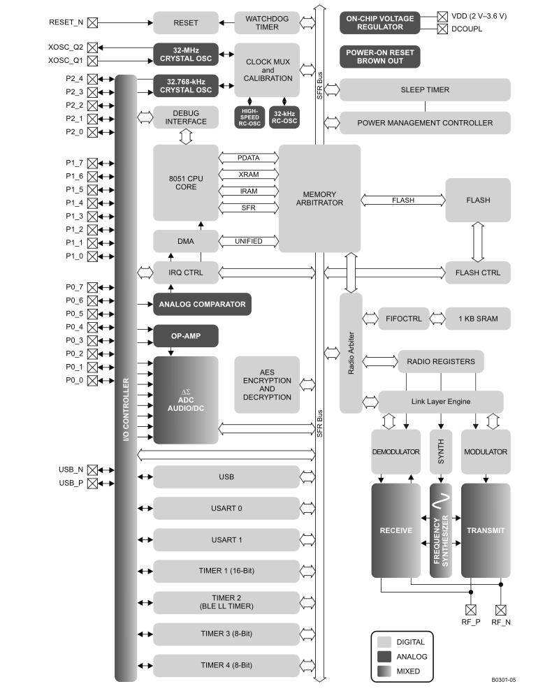
There are 2 variants of CC2540 : CC2540F128, CC2540F256. The only different between the two is the flash space as the name indicates. (128kB vs 256kB). This chip has all major peripherals and hardware capability of modern microcontrollers, as you can see from the functional diagram below. Some highlights:
- USB controller
- 2 hardware UART
- Hardware encryption engine
- bunch of timers
- ADC’s go upto 14bit resolution
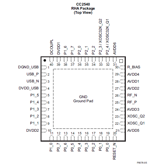
Next, the CC2540′s pin labels in the current package:
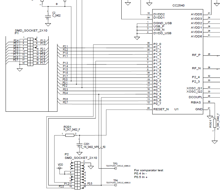
The evaluation module that houses the actual CC2540 chip has all of the IO pins brought out to accessible debug headers. Most of the IO ports are routed to the first SMD socket (evaluation module socket), and is accessible from one of the debug headers located on P18 on SmartRF05EB.
Connectors for Peripherals
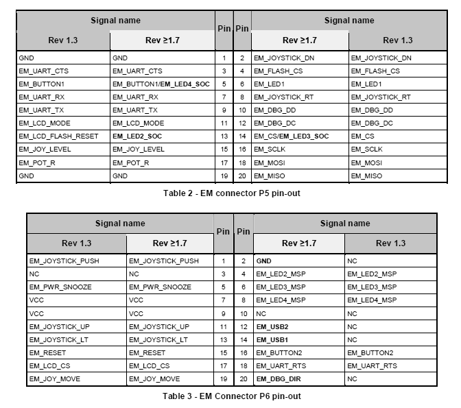
The pins that are brought out via evaluation module connectors are mapped to various peripherals on SmartRF05EB board. The mapping is as follows. On my rev 1.8 board, these pin outs correspond to board connectors P5 and P6, respectively. More details can be found on SmartRF05EB board’s user guide.
The probe connectors give access to these pins, but the mapping from the EM -> Probe pinouts are not straight forward. The probe pin mapping is as follows:
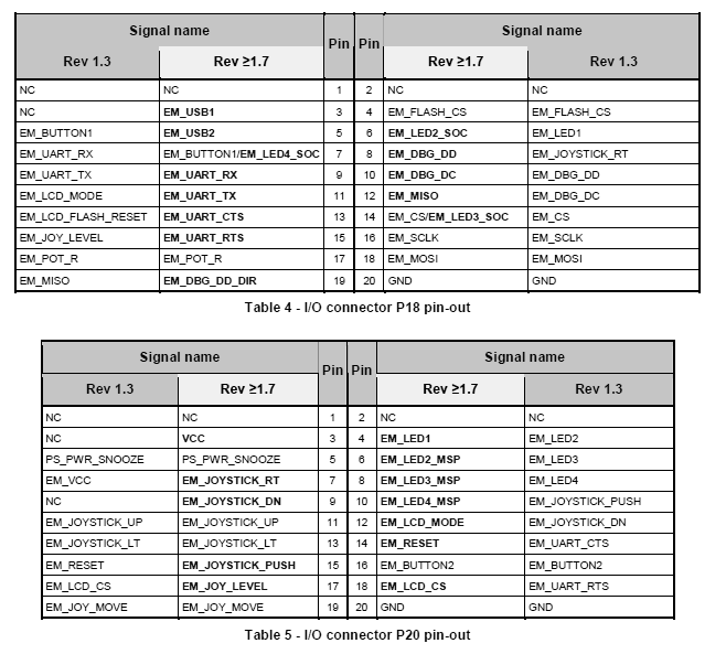
To access a specific pin on from CC2540, we need to do a little mapping of the ports specified from the tables shown above. For example, the IO pin P0.1 from CC2540 corresponds to EM_BUTTON1/EM_LED4_SOC at EM connector pin 5. The same pin corresponds to the pin 7 on the prob connector. I wish the mapping of the pins from the debug headers to the actual chip was more straight forward. I had to trudge through 3 different technical documentations to find this.
I’ll be connecting the pulsesensor to pin P0.7, which corresponds to EM_POT_R (potentiometer) on pin 17 @ P5 on the EM connector and pin 17 @ P18 on the probe connector. In order to disable the onboard potentiometer, I needed to take the jumper off on connector P10 on SmartRF05EB, at position 33-34. The connector P10 is where you can sever or link each individual peripheral that connects to the evaluation board housing CC2540.
